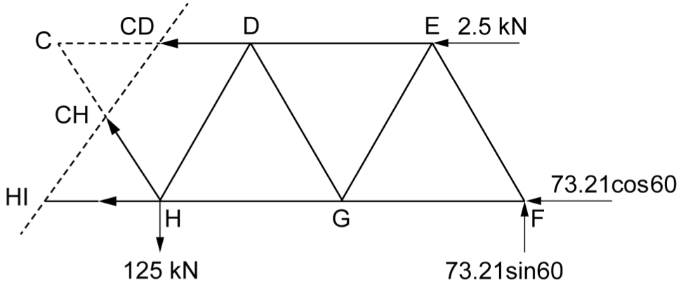
A truss is loaded as shown.

Determine the magnitude and nature of the force in member \(\text{M}\). (6 marks)
--- 24 WORK AREA LINES (style=lined) ---
Show Worked Solution

Find reactions at supports — take moments about \(\text{A}\):
| \(\Sigma M_A\) | \(= 0\) | |
| \(0 = +(9 \times 1.4)+(15\sin60° \times 2.8)-(15\cos60° \times 0.7)-R_B \times 2.8\) | ||
| \(0 = 12.6+36.373-5.25-2.8R_B\) | ||
| \(R_B\) | \(= \dfrac{43.723}{2.8}\) | |
| \(R_B\) | \(= 15.615 \ \text{kN} \uparrow\) |
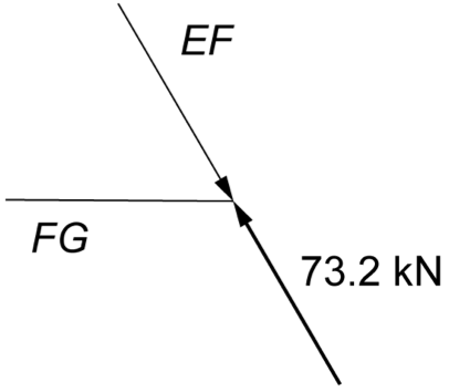
Consider RHS of section plane — sum vertical forces:
| \(\Sigma F_V\) | \(= 0\) | |
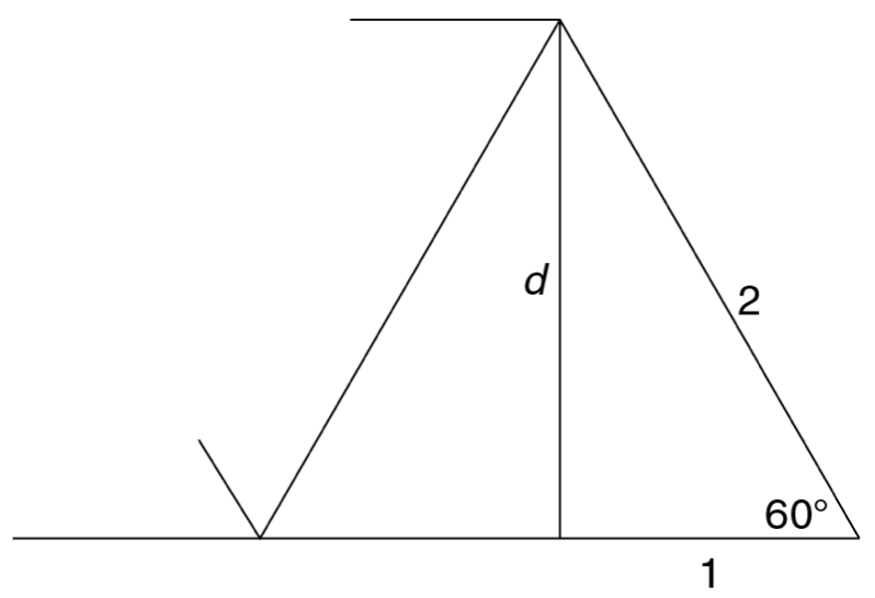
| \(0 = 15.615-15\sin60°-F_M\sin26.565°\) | ||
| \(F_M\) | \(= \dfrac{2.625}{\sin26.565°}\) | |
| \(F_M\) | \(= 5.8697 \ \text{kN}\) | |
| \(F_M\) | \(= 5869.7 \ \text{N (Tension)}\) |
♦♦ Mean mark 51%.

Find \(R_B\) as above \(= 15.615 \ \text{kN} \uparrow\)

Consider Joint C — sum vertical forces:
| \(\Sigma F_V\) | \(= 0\) | |
| \(0 = 15.615-15\sin60°-F_M\sin26.565°\) | ||
| \(F_M\) | \(= \dfrac{2.625}{\sin26.565°}\) | |
| \(F_M\) | \(= 5.8697 \ \text{kN}\) | |
| \(F_M\) | \(= 5869.7 \ \text{N (Tension)}\) |


